2021/04/08
The Ultimate Guide To Actuators
News and Articles
Introduction
Anywhere a machine pushes or pulls, raises or lowers, roughly positions, or rotates a load, an electric linear actuator can be used. Electric linear actuators are devices that provide reliable and precise movement of your equipment, offering total operator control. They have the advantage of being maintenance-free, having a long life span, and being energy efficient. The need for electric actuation has increased exponentially in recent years. Wherever modernity takes hold, automated equipment adjustment and electric actuation are emerging. So wherever you look, you will often find at least one of the three types of electric actuators, electric linear actuator, lifting column, or gear motor, operating in an infinite variety of applications.
TiMOTION is an industry-leading provider of electric linear actuator solutions. Our global team of specialists customizes actuator specifications best suited for medical, industrial, workplace, and home furniture applications. Each type of actuator exhibits both good and bad characteristics that one must weigh when determining the best solution for their application project.
The process of choosing the right electric linear actuation system for your application is one that you must carefully research before purchasing. TiMOTION specializes in partnering with our clients while providing quality solutions for their actuation needs. This guidebook will take you through the components that go into manufacturing an electric linear actuator to provide a better foundation and a clear understanding of how an actuation system works.
Contents |
|
|
|
|
|
|
|
|
|
|
|
|
|
|
|
|
|
|
|
|
|
|


Chapter 1Electric Linear Actuator |
What is an Electric Linear Actuator
An actuator is a device that converts a source of energy into a physical mechanical motion. A linear actuator is an actuator that can move something in a straight line.
Compared to the other two main types of actuators – hydraulic and pneumatic (see Chapter 1 for more) – electric actuators are the most reliable and require almost zero maintenance. Electric actuators are also often far less expensive than their pneumatic counterparts. It’s also much easier to integrate positioning feedback into an electric solution over pneumatic or hydraulic actuators.
How Does It Work
An electric linear actuator converts an AC or DC motor's rotational motion into a linear motion to effectively make products that can pivot in various directions. DC voltage is generally regarded as much safer.
The linear motion is created by rotating the actuator’s screw via the motor. The screw turns either clockwise or counterclockwise, and this causes the shaft (which is a nut on the screw) to move in a line, up and down, creating the push/pull effect for the load.
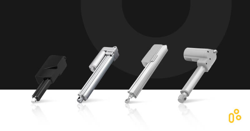
Common Types of Actuators
There are many components and options to an electromechanical linear actuator. As a vertically integrated company, TiMOTION designs and manufactures various linear actuators that are all interchangeably customizable to fit a customer's application needs. Some common styles of electric or electromechanical linear actuators include:
Parallel Drive Actuator
The motor is directly parallel to the drive spindle. Typically, these types of electric linear actuators are spur or spiral gear with more gear ratio options. Parallel drive actuators allow for a broader range of loads and speeds. However, parallel drive actuators with spur gear can operate louder than spiral gear and worm gear driven actuators. Some examples of parallel drive actuators that TiMOTION manufactures can be seen in our TA2P, TA16, TA29, MA2, MA5, and VN1 models.
MA2
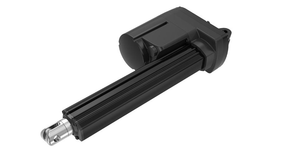
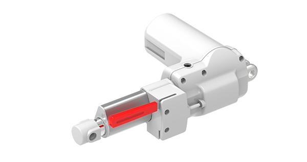
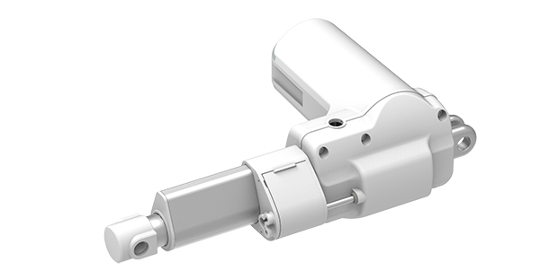
Right-angle or “L” Drive Actuator
The motor is set perpendicular to the drive spindle. Typically, these types of electric linear actuators are worm gear driven. Worm gear-driven motors have fewer gear ratio options. Because of that, they are less efficient than spur gear-driven motors but operate with low noise. One of the key benefits of a worm gear driven, right-angle electric linear actuator is increased self-locking ability. Some examples of right-angle drive actuators that TiMOTION manufactures can be seen in our TA23, TA31, TA37, and TA43 models.
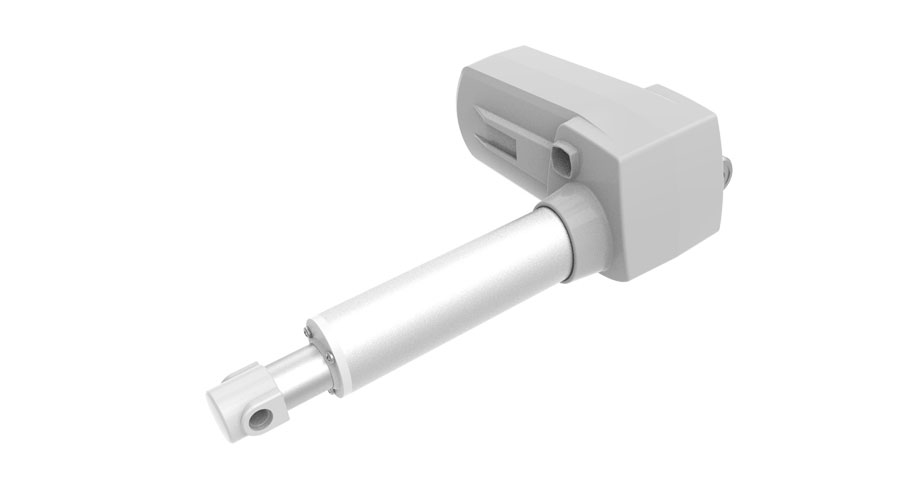
TA37
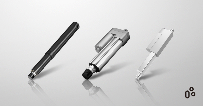
Inline Actuator
An electric inline actuator has a longer retracted length but is explicitly designed to fit into smaller or compact spaces. The inline actuator is typically made up of a motor, planetary gear assembly, and drive spindle. These usually operate at a higher noise level. Our JP3 and JP4 models are examples of inline actuators.
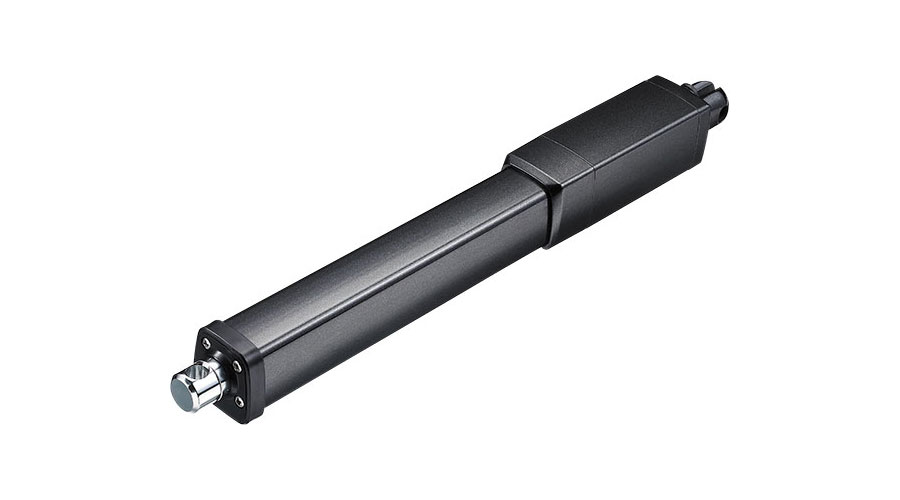
JP4
Gear Motors
Gear motors allow for economical and flexible designs when matching them with various external spindle assemblies. The compact design is typically worm gear driven and an excellent choice for mechanical synchronization. TiMOTION’s TGM1, TGM2, TGM3, TGM4, TGM5, and TGM7 models are examples of gear motors.
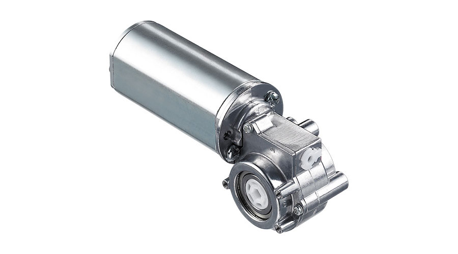
TGM3
Dual Motors
A dual motor linear actuator creates movement in two directions, either individually or simultaneously. They are also typically worm gear-driven motors, which operate at a lower noise level. While these generally are more expensive per unit, the total system cost will be more economical due to fewer parts. Our TT1 model is a remarkable example of a dual-motor linear actuator.
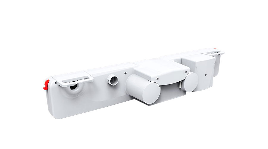
TT1
Linear Slide Actuator
This actuator style creates a linear movement without the use of an outer tube. It utilizes a plastic slide mechanism that travels across the actuator, attached to the frame of common household furniture (such as power recliners and couches), as seen in TA5P actuators.
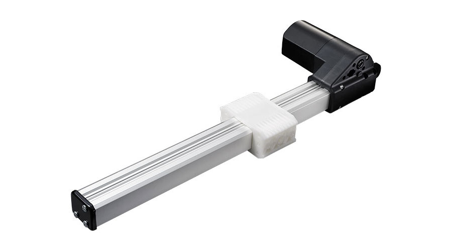
TA5P
Electric Lifting Column
TiMOTION manufactures lifting columns catering to the industrial, medical, and ergonomic markets. An electric column's primary advantage is its ability to lift high loads vertically while retaining a high degree of stability and bending movement compared with linear actuators. Our industrial and medical grade columns are designed for applications such as medical and bariatric beds and height-adjustable industrial workstations, where worker and patient safety is essential. Some examples of these columns are the TL3, TL10H, TL17, TL27, and TL18AC.
Our office ergonomic columns come in various colors, shapes, orientations, as well as two or three stages for BIFMA compatibility, depending on user preference. (The Business and Institutional Furniture Manufacturer’s Association, or BIFMA, is a not-for-profit trade association promoting and maintaining voluntary safety and performance standards for furniture products.) Some examples of TiMOTION’s office ergonomic columns can be seen on the TL4, TL5, TL7, TL9, TL13, TL14, and TL15.
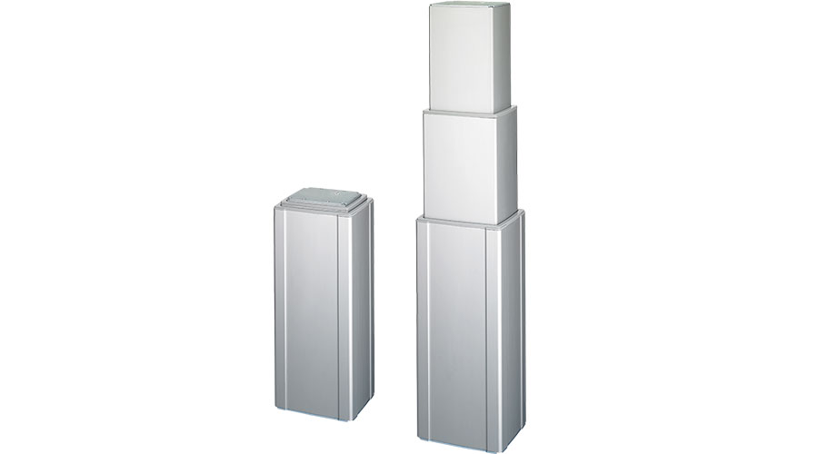
TL3
How to Choose the Right Types of Electric Linear Actuators
An essential part of any successful automation project is choosing the right electric actuator. As you’ve just learned, there are many actuator models – parallel, L-shaped, or inline motor –used in a wide range of applications.
Each project need is unique. To help you select the right actuator, consider the application and its technical constraints: speed, load, duty cycle, available space, environment, and more.
Define the Required Load
The load to be supported is a determining factor in the actuator choice and will define its various components (motor, nut, spindle, gears, ball bearings, etc.). It is crucial to determine which direction the actuator will operate (pull, push, vertical or horizontal movement) and over which length. It will also depend on the diameter of the actuator’s inner and outer tubes. All these factors influence the actuator's ability to lift loads and have an impact on its strength.
Define the Required Speed
The desired speed is a fundamental parameter in the selection of the actuator. Not all mechanisms or materials are compatible with high speeds. High speed with a high load can cause premature wear of the actuator and affect its lifetime. Therefore, each device has speed and load that must not be exceeded to protect it from material damage. This speed depends, among other things, on the pitch and the motor characteristics.
Define the Duty Cycle
The duty cycle defines the ratio between the on-time and off-time of a device and varies considerably from one application to another. The duty cycle is essential to determine the actuator, its materials, and its mechanisms. It helps give the equipment an optimal lifetime and limit mechanical parts' wear or possible overheating.
Electric actuators with parallel motors, for example, with their spur gears, will withstand a higher duty cycle and have a higher number of cycles.
Define the Available Space
The system’s available space also informs the choice of the actuator. In addition to load, stroke, and speed, it is necessary to consider whether the actuator will have to operate in a restricted space and if there are any space restrictions to allow integration into the application.
For example, inline electric actuators, due to the motor's alignment with the spindle, are more compact, making them ideal for tight installation spaces. An actuator's mounting dimensions depend on the mounting configuration (inline, L-shaped, or parallel motor).
Define the Environment
The environment in which the equipment will operate is a crucial parameter in choosing the right electric actuator.
Questions to consider: Does the equipment operate indoors or outdoors? Is it exposed to dust, solid contaminants, or moisture? Does it have to withstand intensive cleaning with detergents or high-pressure cleaning? Depending on the environmental requirements, the materials used and the ingress protection rating (please see Chapter 6 for more) will differ. Does it require a silent operation? For example, L-shaped electric actuators, with their plastic worm gears, provide a quieter movement, ideal for medical or domestic equipment.
The choice of an electric actuator depends on many parameters. It is essential to choose a linear actuator that meets the application requirements. Every application includes a list of conditions that must be met to select the right electric actuator. Budget is also a factor in project planning. Some unavoidable technical constraints will require a larger budget. The important thing is to evaluate all these parameters to create the most suitable device.
Chapter 2Comparison of Different Types of Actuator Systems |
There are many misconceptions or outdated notions involving the three types of actuator motion systems – pneumatic, hydraulic, and electric. While you may think that your application's actuation needs to depend on one specific type of actuator, the march of progress and technological advances permit greater potential interchangeability, creating more than one option for your application project.
Three Types of Actuator Systems
Pneumatic
Composed of a simple piston inside a hollow cylinder, pneumatic linear actuators are widely used in automation because they’re cheap, but they need air piped in. A manual pump or external compressor moves the piston within the cylinder housing. As this pressure increases, the cylinder moves along the piston's axis, creating the linear force needed. It returns to its original retracted length by either a spring-back force or by providing fluid to the piston's opposite side.
Hydraulic
Like pneumatic actuators, hydraulic linear actuators use an incompressible liquid supplied by a pump instead of pressurized air, moving the cylinder in a linear motion. Hydraulic actuators comprise two essential parts: a control device, such as variable throttles (nozzles with slide gates or paired slide valves with an initial axial gap), and an actuation component, such as a piston or controlling valve slide. They are capable of very high forces and long strokes but are not programable.
Electric
Compact and programmable, electric linear actuators are capable of high speed, force, precision, and controlled acceleration and deceleration. Electric actuators take the rotational force of a motor (electrical energy) and convert it into linear movement (torque). By rotating the actuator’s screw via the motor, the nut will move in a lineup and down, creating the load's push/pull effect. Compared to hydraulic and pneumatic, electric actuators are the most reliable and require almost zero maintenance.
Advantages and Drawbacks
Each type of actuator is essential to its appropriate application. Each has its advantages and disadvantages, so be sure to weigh the options before deciding on the right actuator for your project.
|
Characteristics |
Pneumatic |
Hydraulic |
Electric |
|
Complexity |
Simple system composition |
Moderately complex system composition |
Control systems and motion components can work together in multiple complex configurations |
|
Peak Power |
High |
Very high |
High |
|
Control |
Simple valves |
User must |
Flexibility of motion control capabilities with electronic controller |
|
Position Accuracy |
Very difficult to achieve position accuracy |
Mid-stroke positioning requires additional components and user support |
Positioning capabilities and velocity control allow for synchronization |
|
Speed |
Very high |
Moderate |
Moderate |
|
Load Ratings |
High |
Very high |
Can be high depending on the speed and positioning desired |
|
Lifetime |
Moderate |
Long |
Long |
|
Acceleration |
Very high |
Very high |
Moderate |
|
Shock Loads |
Able to handle shock loads |
Explosion-proof, shock-proof, and spark-proof |
Limited ability to handle shock loads |
|
Environmental |
High noise levels |
Hydraulic fluid leaks and disposal |
Minimal |
|
Utilities |
Compressor. power, pipes |
Pump, power, pipes |
Power only option |
|
Efficiency |
Low |
Low |
High |
|
Reliability |
Excellent |
Good |
Good |
|
Maintenance |
High user-maintenance |
High user-maintenance |
Little to no maintenance |
|
Purchase Cost |
Low
|
High
|
High
|
|
Operating Cost |
Moderate |
High |
Low |
|
Maintenance Cost |
Low |
High |
Low |
By deciding what characteristics are non-negotiable from the start, you will begin to rule out particular actuators based on these needs. Should it come down to two specific actuators where both can do the necessary job efficiently, you may want to consider the system's entire cost. This includes the initial investment, maintenance, and repair fees, as well as the cost of potential risks you could take with each motion component system.
Chapter 3Components of an Electric Linear Actuator |
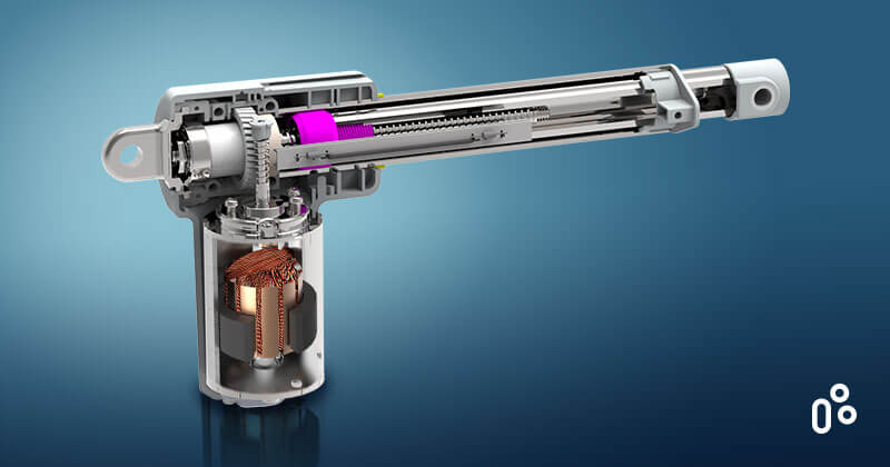
Actuators come in many shapes, sizes, and capabilities. TiMOTION is a vertically integrated company, meaning we can customize, design, and manufacture all of these components in-house for a customer, depending on their application needs.
To best implement innovative and inexpensive automation solutions, it helps to understand an actuator’s strengths and limitations by becoming familiar with its inner workings. Let’s examine the components that comprise an electric linear actuator.
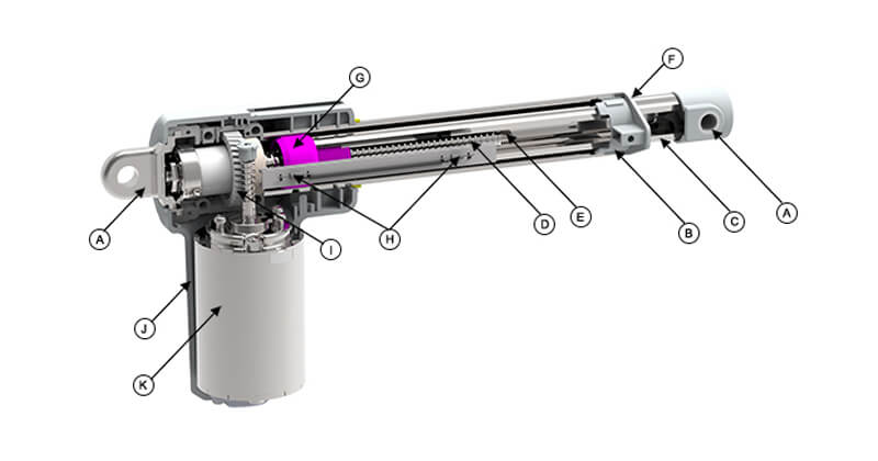
A. Front/Rear Clevis
A clevis is a U-shaped metal piece with holes in each end through which a fastening device, a pin or bolt, is run. Clevis attachments on the front and rear of the actuator allow it to be mounted to the application. Attachment styles from TiMOTION include round, U-shaped (or slotted), or with a punched hole. TiMOTION can customize clevises to fit best the application in use.
B. Outer Tube
This extruded aluminum tube – also known as the cover tube – protects the outside of the linear actuator and houses all of the actuator's inner components.
C. Inner Tube
Also known as the extension tube, drive tube, translating tube, or piston, the inner tube is usually made out of aluminum or stainless steel. While retracted, the inner tube is located with the spindle. This tube is attached to the threaded drive nut and extends and retracts when the nut moves along the rotating spindle.
D. Spindle
A spindle – also known as the lead screw, rotating screw, or lifting screw – is a long, straight rod that turns in a machine or tool. This linear actuator segment rotates, extending or retracting the nut/inner tube, which creates a linear motion. Our steel spindle ensures durability and strength. The spindle can be threaded in different ways for various load and speed capabilities.
E. Safety Stop
The safety stop’s function – located on the spindle’s end – prevents the overextension of the inner tube.
F. Wiper
A wiper is a sealing component attached to the end of the outer tube, which prevents contaminants like dust and liquids from entering the actuator's spindle area. It also ensures a proper seal between the inner and outer tubes, influencing the linear actuator's IP rating. TiMOTION’s electric linear actuators can be rated anywhere between IP42, IP66, IP68, and IP69K. (See Chapter 6 to learn more about the IP rating.)
G. Drive Nut
The nut, which can be acme or ball screws, is attached to the inner tube and travels along the spindle. The nut is the component that allows extension or retraction of the inner tube. It can be made of metal or plastic and is sometimes keyed to prevent inner tube rotation.
H. Limit Switches
Limit switches control the fully extended and retracted inner tube position by electrically cutting current to the motor. These switches prevent the actuator from overextending or over-retracting. In addition to cutting current, limit switches can also be used as a signal-sending device.
I. Gear
A gear is made of steel or plastic and mates with other gears to alter the relation between the speed of a driving mechanism (such as the engine of a vehicle) and the speed of the driven parts (the vehicle’s wheels). The gear connected to a power source, such as the motor, is called the "drive gear". TiMOTION has different gear options depending on the application.
J. Motor Housing
The motor housing contains all the internal parts of the gear motor without leaving anything exposed to external damage. TiMOTION's motor housing is typically made of high-quality plastic.
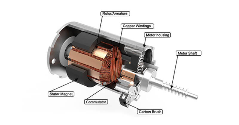
K. DC Motor
The DC (Direct Current) motor generates all of the electric linear actuator’s power. There are several types of DC motors, but TiMOTION uses brushed DC motors, which are composed of:
- Stator:
This stationary, outside portion of the motor consists of the motor housing, two permanent magnets, and motor caps. The stator generates a stationary magnetic field that surrounds the rotor.
- Rotor:
The rotor – also known as the armature – is the inner part of the motor that rotates. It mainly consists of silicon steel laminate, a motor shaft, a commutator, and copper windings.
- Commutator:
The commutator is a pair of plates attached to the motor shaft. These plates provide two connections for the coil of the electromagnet. The commutator reverses the motor's polarity and essentially keeps the motor rotating without losing torque.
- Carbon brushes:
Carbon brushes use sliding friction to transmit electrical current from the stator to the rotor in the motor.
- Motor Shaft:
The motor shaft connects the gear motor to the bottom of the stator on the DC motor.
Note: Alternating Current Motors (AC Motors) is also an option that TiMOTION manufactures. This type of motor is an available option that can be seen in our MA1 model.
Chapter 4Safety Feature Options |
TiMOTION believes that quality and safety go hand in hand with design and functionality. As a vertically integrated electric actuator manufacturer, we can customize these features to meet customers' needs.
Depending on the environment in which the actuator operates and the duress it undergoes, it’s wise to reinforce that actuator’s stability and strength. When purchasing an actuator, some safety feature options to consider are:
Overload Clutch
The overload clutch is a built-in device that slips when the electric actuator reaches a pre-set load limit. It connects and disconnects the motor from the lead screw. This slippage prevents the linear actuator from incurring possible damage. The overload clutch is a great safety feature option on our MA1 industrial linear actuator.
PTC Thermistor
A PTC Thermistor essentially acts as a fuse that cuts the motor's power, protecting the motor from overheating and burning out. Our electric motors have a UL certification option that includes a PTC Thermistor installed inside. For over a century, Underwriter Laboratories (UL) has been a world leader in product safety and certification to nationally recognized safety and suitability standards. TiMOTION ensures our products go through proper outside testing to receive UL certification.
Safety Nut
A safety nut is a metal-reinforced acme drive nut used to help the linear actuator support a higher load. A safety nut is recommended for loads of 6,000N or more. TiMOTION's durable electric linear actuators can also add this feature to ensure the actuator's strength and integrity.
Push-Only Nut
A standard drive nut will have threads to screw into the extension tube, whereas a “push only” nut won’t have threads. This prevents obstructions (animals, people, other furniture, etc.) from being damaged by a retracting linear actuator system. An example of where this can be helpful is a recliner. If the recliner's foot is going from an extended to a retracted position and there is an object below the chair's feet, the chair's foot will not continue to push force on the object with which it comes into contact. Our TA5P, TA6, and TA14 indoor linear actuators would be used in this sort of application.
Quick Release
The quick-release is a handle or cable that allows the actuator to be swiftly back-driven when released. The quick-release is designed mainly for medical bed applications when the backrest of a medical bed needs to be quickly laid flat (in case of emergency CPR). Our medically certified linear actuators can come with this option (subject to application needs) seen in our TA31 and TA15 models.
Manual Release
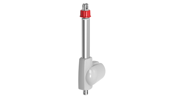
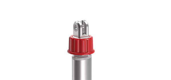
The manual release is designed primarily for a medical patient hoist system. The manual release allows the extension tube (inner tube) to release from the front attachment (clevis) and spin freely. The manual release allows the linear actuator to back-drive freely and to manually lower a patient from the patient hoist system. This feature can be easily customized in our TA23, TA36, and TA37 models.
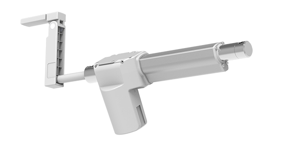
Manual Crank
The manual crank is a safety feature designed mainly for the medical industry. It allows a medical practitioner to manually operate the bed position in case of emergency or power outages. TiMOTION's TA10 medical actuator and MA1/MA2 industrial actuators have the manual crank option to customize depending on the customer's application needs.
Spindle Brake
A spindle brake is a unidirectional no-back type brake, installed and wrapped around the worm gear. It is activated automatically by pinion winding and then released when the motor turns.
Motor Brake
The motor brake is installed either on the top or bottom of the motor shaft. It depends on whether the application will be pushing or pulling the load. The motor brake gives the electric actuator the added durability that enhances the self-locking force of the actuator. Since TiMOTION manufactures durable products, most of our electric actuators come standard with a motor brake.
Electromechanical Brake
The electromechanical brake slows or stops the motor using electromagnetic force to apply mechanical resistance to the spindle. The electromechanical brake is also installed on the bottom of the motor shaft. This is another excellent safety feature option on our MA1 industrial linear actuator.
Mechanical Brake
A mechanical brake can be added to reinforce the electric actuator's stability when the back drive is potentially a factor with high-weight loads.
Chapter 5Load and Speed |
There are many factors to consider when choosing the right electric linear actuator system for your application. By tailoring various combinations of spindle type, spindle specs, motor revolutions per minute (RPM), gear ratio, and the amount of power supplied to the actuator, TiMOTION can control the load and speed capabilities of the actuator. These characteristics are all dependent upon each other to operate a quality and durable linear actuator.
Types of Actuator Spindle
The type of spindle (or screw) will partly determine how fast the electric actuator moves and its load capability. TiMOTION produces electric actuators that feature one of two types of spindles, lead screws, and ball screws. There are three thread types for a lead screw: square thread, acme thread, and buttress thread.
Lead Screw
TiMOTION produces a lead screw with Acme thread (to fit an acme nut). Acme threads have a high load capacity but are not as fast as a ball screw due to increased friction caused between the nut and thread. However, the Acme lead screw is a more economical and highly reliable solution that we can pass along to our customers. The majority of the electromechanical actuators that TiMOTION manufactures use the Acme threaded lead screw, as seen in our models, including the TA2, TA4, TA6, and TA23.
Ball Screw
The ball screw creates less friction than the acme screw because the threaded shaft provides a circular pathway for ball bearings (in a ball nut), which acts more precisely than the sliding friction caused by the acme nut. Because of this, the ball screw is more efficient and able to move at high speed. However, there is generally no self-locking force on a ball screw, so a brake mechanism can help with the back drive and holding the load in place. A ball screw is an option used commonly in our MA1 linear actuator model.
Spindle Specs
The spindle specifications also have a large effect on how fast the actuator moves, but mostly on how much load it is capable of holding. The specs on a spindle (or screw) include the pitch, lead, and the number of starts. The pitch is the axial distance from a crest on a screw thread to an adjacent thread's equivalent crest. The lead is the linear distance the screw travels in one complete turn (360 degrees) on the shaft. The start is the number of independent threads wrapped around the screw.
What does all of this mean? The angle of the thread determines how fast the nut travels up and down the shaft. The steeper the angle, the faster it moves, and vice versa. The more starts there are on the spindle, the steeper the thread angle. However, there is a trade-off between speed and self-locking ability. The faster the nut travels up and down the spindle, typically means the self-locking force decreases (the natural ability to hold a load in place once the nut comes to a stop).
RPM and Gear Ratio
Another thing to consider when controlling an actuator's speed and load is adjusting the gear set's RPM and gear ratio. The gear ratio is the ratio of the number of revolutions per minute (RPM) of the driver vs. the driven gear's RPM. For example, if a driver spur gear has 12 teeth on it and the driven spur gear has 24 teeth, the driven spur gear is twice as big as the driver gear. Since the drive gear must turn two times for every one turn of the driven gear, it has a 2:1 gear ratio.
There can also be additional gears added into the equation, depending on the trade-off between force and speed required, because force and speed are linked in an actuator by the formula “Mechanical Power = Force * Speed.” So, what does all of this mean? Suppose the load required on a particular application is heavy. In that case, TiMOTION can add more gears and adjust the gear ratio to create more torque on the actuator, which ultimately puts more force on the spindle allowing it to travel.
Mechanical Power Required
When manipulating a linear actuator's load and speed, one can also consider the amount of mechanical power required for the application (the power is measured in watts). The main point to remember about current, speed, and load in DC motors is that when the load increases, the current will increase, and the speed will then tend to decrease (as shown in the charts below). Besides this primary relationship, many other electromechanical parameters influence load and speed, like the kind of power supply used or the motor's efficiency. TiMOTION’s engineers work hard to select the right parameters to meet our clients' application needs.
TiMOTION offers power supplies to support our 12V DC, 24V DC, or 36V DC linear actuators. Since most of TiMOTION's actuators run on direct current (DC) power, our control boxes can convert alternating current (AC) power to DC power so customers can plug their applications into the wall. TiMOTION can integrate SMPS transformers (switch mode power supply) and toroidal transformers into the control boxes. SMPS transformers support 110V AC and 220V AC inputs, allowing our customer to plug their products into different outlets worldwide.
Below are three charts to help with term usage and conversions. The first is common voltage expressions that can be used interchangeably, the second is the conversion of Newton (N) to Pounds (Lbs.) and kilograms (kg), and the last is the conversion of Millimeters (mm) to Inches (In):
'
Voltage Expressions
| 12 Volts DC | 12V DC | 12 VDC |
| 24 Volts DC | 24V DC | 24 VDC |
| 36 Volts DC | 36V DC | 36 VDC |
| 48 Volts DC | 48V DC | 48 VDC |
| 110 Volts AC | 110V AC | 110 VAC |
| 220 Volts AC | 220V AC | 220 VAC |
Weight Conversion (N to lbs. and kgs)
| 1 Newton (N) | .22481 Pound (lbs) |
| 1 Newton (N) | .1 Kilogram (Kg) |
Distance (mm to in.)
| 1 Millimeter (mm) | .03937 Inch (in) |
Chapter 6IP Rating |
Not only do the internal parts of an actuator affect its life span, but the ability to protect the actuator from intrusions such as solid objects and liquids will ensure its' long-lasting life as well. TiMOTION helps ensure this by adding a protective seal around the outside of our electric linear actuators and lifting columns.
What is IP Rating
Depending on the application's environment, we can customize the protection level around the outside of the linear actuator. These levels are calculated based on the IP Rating. The IP rating stands for Ingress Protection rating (sometimes also interpreted as “International Protection” rating) and usually consists of two digits following "IP" which describes its level of protection.
What Does It Mean Between Different IP Rating
The first digit indicates the level of protection against the ingress of solid foreign objects such as dust and debris. This scale ranges from 0 (not protected) to 6 (high protection from dust). The second digit indicates the level of ingress protection against liquids such as water. This protection scale ranges from 0 (not protected) to 8 (high protection level from liquids).
The IP rating improves the lifetime of equipment, as well as the safety requirements for users. To ensure this, TiMOTION subjects all its finished products to pre-commercialization tests in strict circumstances beyond the actual conditions of use, thus allowing us to be confident in providing quality products.
How To Read An Ingress Protection Rating
| IP | 6 | 8 |
|
Ingress Protection |
First Digit: Solids Protection |
Second Digit: Liquids Protection |
Common IP Ratings
IP42
The IP42 protection typically applies to indoor applications where dust and water are not large factors, such as in a TV lift, household couch, chair, or adjustable bed. These applications are often used with our TVL3, TA5P, TA6, and TA14 linear actuator models.
IP54
The IP54 rating is more universal because it has a higher level of protection, allowing the actuator to operate in a more volatile environment such as a hospital, dental office, or warehouse. These applications are often used with our TA4, TA23, etc., actuator models.
IP66
The IP66 rating is one of our highest-level seals, which makes it a waterproof linear actuator. It can be placed typically into an outdoor environment where harsh conditions are present such as farm construction sites. Also, IP66 can be very important for medical and patient mobility equipment such as pool lifts and medical beds. These types of applications are often used with our TA16, TA23, and TA31 actuator models.
IP69K
We also offer an IP69K level of protection, considered one of the industry's highest. IP69K is a protection provision of high temperatures and pressured water. An actuator with this protection level can be sprayed down with a high-pressure hose, such as in an agricultural setting where dust, dirt, and chemical levels are high. The IP69K rating is an optional sealant on our MA1, MA2, MA5, JP3, and JP4 actuator models.
Chapter 7Feedback Sensors |
The process of choosing the right electric linear actuation system for your application is one that you must carefully research before purchasing. TiMOTION is proud to offer many customization options, in addition to knowledgeable customer service, to help you create the perfect solution.
Before committing to the specific model for your needs, we believe it’s essential for our customers to inform and educate themselves about an electric linear actuator's vital components and functions. This chapter highlights a critical discussion regarding the four primary position feedback sensors used within TiMOTION’s linear motion systems.
How It Works
When equipped with feedback sensors, an electric linear actuator can actively communicate its stroke position to the control system (sometimes referred to as positioning). These output sensors also allow for the control box to precisely regulate the actuator’s stroke at all times.
While this is not required on all linear actuators, positional sensors are required on those with more complex functionality. For example, if an actuator needs to move synchronously with another, feedback sensors are necessary to monitor and ensure both linear actuators remain in sync, regardless of differences in load.
Additionally, feedback sensors are crucial for memory positioning and other special features that require knowing where the actuator’s stroke position is at all times. This can include but is not limited to motor speed, conditional movement, and other features.
Common Types of Actuator Feedback Sensors
Hall Effect Sensors
Hall Effect sensors are TiMOTION’s most recommended type of positional sensors for electric actuators because they are small enough to fit in compact spaces, providing higher resolution and digital output for positioning and synchronization. Note: TiMOTION’s control systems are designed to integrate with Hall sensors only. Our control systems will not register feedback from any other type of sensor.
These Hall Effect sensors are activated by a magnetic field, comprised of two critical characteristics: flux density and polarity. The output signal from a Hall Effect sensor is the magnetic field density function around the device. When the magnetic field density around the sensor exceeds a certain pre-determined threshold, the sensor detects it and generates an output voltage called the Hall Voltage, or VH.
Commonly used due to their cost-efficiency, Hall Effect sensors also maintain their quality over time and generally have long lifespans.
Potentiometers
Potentiometers, also known as POT sensors, are generally the most commonly used output sensor in the industrial marketplace. They have a wiper contact linked to a mechanical shaft that can either be rotational or linear in their movement. This causes the resistance value between the wiper and the two end connections to change, giving an electrical signal output proportional to the actual wiper position on the resistive track and its resistance value.
In other words, resistance determines position. As the linear actuator leads screw turns, the resistance value between the wiper and the two end connections will change. Each resistance value will correspond with the position of the linear actuator’s stroke.
One advantage of the POT sensor versus a Hall sensor is that when the power is off, the POT will keep the position's information, while a Hall sensor will lose the positional information and need to be reset. However, potentiometers are slightly less accurate in their readings than the Hall Effect sensor due to the initial installation process. Yet, this is not detrimental to the overall position reading.
Reed Sensors
Reed sensors are magnetic feedback sensors. An applied magnetic field operates an electrical switch, and the sensor as a whole contains a pair of contacts on ferrous metal reeds in a hermetically sealed glass envelope. The contacts may be normally open, closing when a magnetic field is present, or vice versa. The switch may be actuated by a coil, making the reed switch return to its original position. With force from each rotation of the lead screw and position of the linear actuator stroke length, the reed switch will open or close.
TiMOTION specifically uses its Reed sensors inside the handsets with a safety key function to send a signal when the key has been removed or uses Reed sensors to adjust the end of the stoke.
Optical Sensors
Optical sensors are also occasionally used in TiMOTION’s electric actuators. An optical sensor functions by converting light into an electronic signal. As a lead screw rotates, a light-blocking wheel will also rotate at the same time, blocking the light to the optical coupler. This optical coupler will send a signal each time it senses the light being blocked. The light-blocking wheel revolutions will cause the optical coupler to send twenty-five signals each full revolution.
Conclusion
We hope this guidebook has helped you develop a better understanding and foundation for electric linear actuators and their incorporation into linear motion systems. TiMOTION is a vertically integrated, electric linear actuator and control system manufacturer with the ability to customize products to meet your specifications.
We understand that the right technology can solve nearly any problem and that drop-in replacement, customizable electric linear actuators are used increasingly in applications that have outgrown pneumatics and hydraulics. TiMOTION strives to provide the highest quality, customizable components at competitive pricing. For more information, visit us online today at TiMOTION.
Related Articles

Why TiMOTION is the ideal partner for your automation projects

Part 2: Components Of An Electric Linear Actuator
Part 1: What is an Electric Linear Actuator? Definition & Types Explained
Introduction- Get The Essential Facts About Actuators

IP54 to IP69K Waterproof Linear Actuators

12V Linear Actuators: Power from 1000N to 10000N
TiMOTION Compact Linear Actuators: Applications and Models

Part 5: Dustproof And Waterproof Linear Actuator's IP Rating

10 Reasons To Choose Electric Linear Actuators
