2021/04/04
Part 4: Linear Actuator Guide: Screw Types, Load, Speed, Gear & Power
News and Articles

Whether you are working on your company’s next large project or a “do it yourself” (DIY) task at home, there are many factors to consider when choosing the right electric linear actuator system for your application.
By tailoring various combinations of spindle type, spindle specs, motor revolutions per minute (RPM), gear ratio, and the amount of power supplied to the actuator, TiMOTION can control the load and speed capabilities of the actuator. These characteristics are all dependent upon each other to operate a quality and durable linear actuator.
Understanding Lead Screws and Ball Screws
The type of spindle (or screw) will partly determine how fast the electric actuator moves and its load capability. TiMOTION produces electric actuators that feature one of two types of spindles—lead screws, and ball screws.
1.Lead Screw
A lead screw relies on direct surface-to-surface sliding contact between the screw shaft and the nut to generate linear displacement.
- How it works
- Mechanical Interface: The threaded shaft meshes directly with an internal mating thread inside the nut (most commonly matching an Acme nut).
- Transmission Mechanism: When the motor rotates the screw shaft, the nut is mechanically constrained from turning with it. The rotating helical flank of the screw pushes directly against the nut's thread flank via sliding friction, driving the nut linearly along the axis.
- Key Characteristics
- High Static Holding Force (Self-Locking): The extensive contact area and sliding friction of Acme threads naturally resist back-driving. When power is cut, the nut holds its position under load without requiring an external mechanical or electromagnetic brake.
- Cost Efficiency and High Reliability: With no loose rolling elements or complex recirculating channels, the mechanism is mechanically straightforward, economical to produce, and resilient in demanding operational environments.
- Speed and Efficiency Limits: Sliding friction generates more heat and resistance than rolling mechanisms, resulting in lower efficiency (typically 30%–50%) and limiting high-speed actuation.
TiMOTION produces a lead screw with Acme thread (to fit an acme nut). Acme threads have a high load capacity but are not as fast as a ball screw due to increased friction caused between the nut and thread. However, the acme lead screw is a more economical and highly reliable solution that we can pass along to our customers.
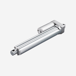
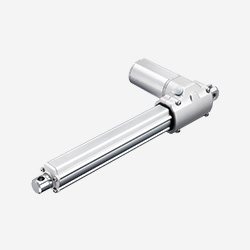
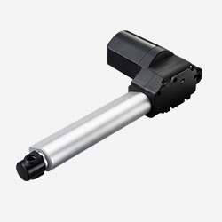
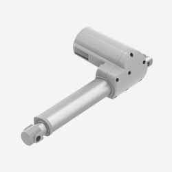
The majority of the electromechanical actuators that TiMOTION manufactures use the acme threaded lead screw, as seen in our TA2, TA4, TA6, TA23, and many more models.
TA2 |
TA4 |
 |
 |
TA6 |
TA23 |
 |
 |
2.Ball Screw
A ball screw replaces sliding friction with rolling friction by introducing spherical ball bearings between the screw shaft and the nut.
- How It Works
- Mechanical Interface: Both the screw shaft and the nut feature precision helical raceway grooves. The space between these matching tracks is filled with a continuous train of hardened steel ball bearings.
- Transmission Mechanism: As the screw rotates, the ball bearings roll along the raceways (rolling friction), smoothly driving the nut along the shaft with minimal resistance.
- Recirculation System: An integrated return circuit (such as return tubes or deflectors) guides the balls from the trailing end back to the leading end of the nut, creating an uninterrupted, closed-loop rolling cycle.
- Key Characteristics
- High Mechanical Efficiency and Speed: Rolling friction creates minimal drag, allowing ball screws to achieve mechanical efficiency exceeding 90%. This permits rapid linear travel and higher duty cycles with reduced motor torque.
- No Natural Self-Locking (Prone to Back-Driving): Because rolling resistance is extremely low, external axial loads can easily push the nut backward and cause the screw to freewheel. To prevent back-driving and hold the load securely when stopped, actuators utilizing ball screws typically integrate an electromechanical brake mechanism.
- Higher Precision and Cost: Precision ball tracks and recirculation hardware require tight tolerances, clean lubrication, and proper sealing, leading to higher manufacturing costs compared to standard lead screws.
The other type of screw that TiMOTION utilizes within its electric linear actuators is the ball screw. The ball screw creates less friction than the acme screw because the threaded shaft provides a circular pathway for ball bearings (in a ball nut), which acts more precisely than the sliding friction caused by the acme nut. Because of this, the ball screw is more efficient and able to move at high speed.
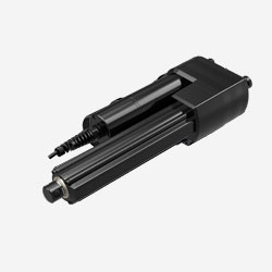
However, there is generally no self-locking force on a ball screw, so a brake mechanism can help with the back drive and holding the load in place. A ball screw is commonly used in our MA1 linear actuator model.
MA1 |
 |
The table below summarizes the key operational and mechanical differences between lead screws and ball screws:
|
Feature |
Lead Screw |
Ball Screw; |
|
Contact Mechanism |
Direct sliding contact (sliding friction) |
Recirculating ball bearings (rolling friction) |
|
Mechanical Efficiency |
Lower (typically 30%–50%) |
High (exceeding 90%) |
|
Self-Locking Force |
High natural resistance to back-driving; holds position without external brakes |
None; easily back-drives under load |
|
Braking Requirement |
Generally not required |
Requires an electromechanical brake to hold static loads |
|
Precision & Tolerances |
Standard mechanical tolerances |
High precision with minimal backlash |
Spindle Specifications in Linear Actuators: How Lead Screws and Ball Screws Balance Speed and Load Capacity
Whether designing linear actuator lead screw systems for high holding force or deploying linear actuators with ball screws for rapid transit, spindle geometry directly dictates mechanical output. Spindle dimensions determine travel velocity, continuous load rating, and the actuator’s static load-holding behavior.
Key Spindle Dimensional Specifications
Three foundational geometric parameters define the profile of any actuator screw shaft:
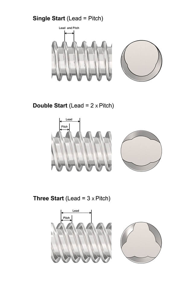
- Pitch: The axial distance measured from the crest of one thread to the corresponding crest of an adjacent thread.
- Lead: The linear distance the nut advances along the shaft during a single complete 360 degrees rotation.
- Number of Starts: The count of individual, independent helical threads wrapped around the spindle shaft.
Formula: Formula: Lead = Pitch x Number of Starts
(On a single-start screw, lead equals pitch; adding starts increases the lead without changing the thread spacing.)
Thread Angle and Travel Speed
The mechanical interaction between lead and diameter determines the helix (thread) angle:
- Steeper Thread Angles: Produced by higher leads or multi-start configurations. Each motor revolution translates into greater linear displacement, enabling the actuator to extend and retract at higher speeds.
- Shallower Thread Angles: Characteristic of low-lead, single-start designs. The nut advances less distance per revolution, resulting in slower speeds but higher mechanical advantage.
Performance Trade-Off: Speed vs. Self-Locking Ability
Selecting spindle dimensions requires balancing travel velocity against static holding safety:
- High-Speed Configurations (Steep Angle / High Lead):
- Advantage: Faster stroke cycles.
- Drawback: Lower natural friction reduces the self-locking force—the actuator's passive resistance against back-driving when stationary.
- High-Holding Configurations (Shallow Angle / Low Lead):
- Advantage: Maximum friction and mechanical leverage, significantly increasing self-locking capability to keep heavy loads firmly supported when the motor stops.
- Drawback: Lower maximum linear velocity under the same motor RPM.
RPM and Gear Ratio in Electric Linear Actuators
Another thing to consider when controlling an actuator's speed and load is adjusting the gear set's RPM and gear ratio.
The gear ratio is the ratio of the number of revolutions per minute (RPM) of the driver vs. the revolutions per minute (RPM) of the driven gear. For example, if a driver spur gear has 12 teeth on it and the driven spur gear has 24 teeth, the driven spur gear is twice as big as the driver gear. Since the drive gear must turn two times for every one turn of the driven gear, it has a 2:1 gear ratio.
There can also be additional gears added into the equation, depending on the trade-off between force and speed required, because force and speed are linked in an actuator by the formula “Mechanical Power = Force * Speed.” So, what does all of this mean? Suppose the load required on a particular application is heavy. In that case, TiMOTION can add more gears and adjust the gear ratio to create more torque on the actuator, which ultimately puts more force on the spindle allowing it to travel.
Calculating Power Requirements and Power Supply Solutions for Electric Actuators
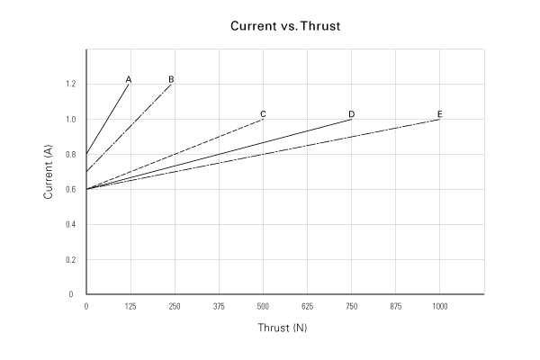
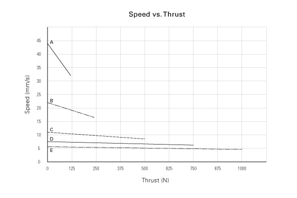
When manipulating a linear actuator's load and speed, one can also consider the amount of mechanical power required for the application (the power is measured in watts). The main point to remember about current, speed, and load in DC motors is that when the load increases, the current will increase, and the speed will then tend to decrease (as shown in the charts above).
Besides this primary relationship, many other electromechanical parameters influence load and speed, like the kind of power supply used or the motor's efficiency. The engineers of TiMOTION are in charge of selecting the right parameters to meet our client's application needs.
TiMOTION offers power supplies to support our 12V DC, 24V DC, or 36V DC linear actuators. Since most of TiMOTION's actuators run on direct current (DC) power, our control boxes can convert alternating current (AC) power to DC power so customers can plug their applications into the wall. TiMOTION can integrate SMPS transformers (switch mode power supply) and toroidal transformers into the control boxes. SMPS transformers support 110V AC and 220V AC inputs, allowing our customers to plug their products into different outlets worldwide.
Below are three charts to help with term usage and conversions. The first is common voltage expressions that can be used interchangeably, the second is the conversion of Newton (N) to Pounds (Lbs.) and kilograms (kg), and the last is the conversion of Millimeters (mm) to Inches (In):
Voltage Expressions
| 12 Volts DC | 12V DC | 12 VDC |
| 24 Volts DC | 24V DC | 24 VDC |
| 36 Volts DC | 36V DC | 36 VDC |
| 48 Volts DC | 48V DC | 48 VDC |
| 110 Volts AC | 110V AC | 110 VAC |
| 220 Volts AC | 220V AC | 220 VAC |
Weight Conversion (N to lbs. and kgs)
| 1 Newton (N) | .22481 Pound (lbs) |
| 1 Newton (N) | .1 Kilogram (Kg) |
Distance (mm to in.)
| 1 Millimeter (mm) | .03937 Inch (in) |
FAQs: Choosing Between a Linear Actuator Lead Screw and Ball Screw
Selecting the right drive mechanism is critical to ensuring your motion system achieves optimal performance, operational life, and cost-efficiency. Here are quick answers to the most common questions engineers ask when evaluating a linear actuator lead screw versus linear actuators with a ball screw:
Q1. How do environmental durability and maintenance requirements differ between a linear actuator lead screw and a ball screw drive?
A linear actuator lead screw tolerates dirty, dusty environments with virtually zero maintenance thanks to its solid nut design. In contrast, linear actuators ball screw setups require regular lubrication and tight dust seals to prevent particulates from damaging the recirculating bearings.
Q2. Which drive operates more quietly between a linear actuator lead screw and a ball screw actuator?
A linear actuator lead screw delivers near-silent motion due to smooth surface sliding, whereas linear actuators ball screw units produce noticeable acoustic noise from the internal steel balls cycling through return tracks.
Q3. When should an engineer prioritize linear actuators with a ball screw over a lead screw design?
Opt for linear actuators ball screw mechanisms when high duty cycles, continuous operation, and minimal thermal buildup are required, while reserving a linear actuator lead screw for intermittent, noise-sensitive, or self-locking applications.
Partner with TiMOTION for Customized Electric Linear Actuator Solutions
We hope this has helped you develop a better understanding and foundation for electric linear actuators. In our next installment, we will look at the levels of IP ratings for liquid and dust protection that can be added to an electric actuator, as well as lubrication that goes into a linear actuator.
If you have further questions and/or would like help with your next application, TiMOTION would be glad to assist you. We specialize in partnering with our clients while providing quality solutions for their linear motion system needs.
Related Articles

Why TiMOTION is the ideal partner for your automation projects

Part 2: Components Of An Electric Linear Actuator

Part 1: What is an Electric Linear Actuator? Definition & Types Explained

Introduction- Get The Essential Facts About Actuators

IP54 to IP69K Waterproof Linear Actuators

12V Linear Actuators: Power from 1000N to 10000N

TiMOTION Compact Linear Actuators: Applications and Models

Part 5: Dustproof And Waterproof Linear Actuator's IP Rating

10 Reasons To Choose Electric Linear Actuators

 Contact Us
 Locations